Round Tube Baffle Ceiling Design: Diameter Changes the Choice

For a perforated round-tube ceiling, the diameter choice is 50 or 70 mm. We offer other diameters with a plain face, so increasing the diameter also requires a decision about the acoustic role of the tubes. For TUODELI, the starting point in round tube baffle ceiling design is the relationship between the rounded lines the architect wants to see and the face needed for the proposed ceiling.
Consider diameter and centre spacing together. Widening a tube without moving its centreline widens the band seen from below and reduces the opening beside it. The calculation gives an architect a useful comparison of visual density. Air movement, absorption, sprinklers and service access still require their respective design checks; the geometric opening cannot establish those results.
A circular tube changes the section you are choosing
A round tube has one diameter instead of separate width and depth
A 70 mm diameter fixes the 70 mm underside and matching depth, unlike a rectangular blade whose width and depth can be chosen separately. A 70 mm underside at 200 mm depth therefore requires another profile. When substituting the tube for a blade, assess the changed underside visible from the room and the opening above it.
Our aluminum round tube baffle ceiling has diameters from 25–120 mm, allowing the rounded line and the interval between rows to be varied separately. Smaller diameters give finer stripes. Enlarging the circle broadens the stripe and increases its vertical depth equally; row spacing is therefore not the only available visual adjustment.
For a narrow underside beneath a deep screen, choose a deeper profile from the metal baffle ceiling range. Enlarging a circle increases depth and width together, which can produce a wider underside than the original narrow blade was intended to show. Select the tube where those circular proportions and the coupled dimensional change suit the design.
A round section does not mean that the whole run is curved
Tube diameter describes a cross-section, whereas a curve in plan or elevation describes the path or outline of the member. Specifying the diameter of straight circular tubes still gives a straight row. A radius and curved arrangement require their own definition; neither is contained in the diameter.
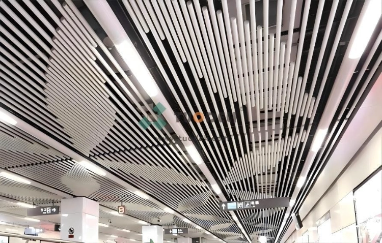
Include the arrangement alongside the section in the description. “70 mm round tubes in straight parallel rows” establishes what the circle is and where it runs. To describe a sweep, add the geometry that defines that sweep. Otherwise, “round” may be read as a different ceiling concept from the one the designer intended, without that change having been assessed.
Diameter and pitch produce the visible stripe together
Centre spacing and clear spacing describe different openings
Pitch is measured from one tube centre to the next, while clear gap is measured between the nearest surfaces. For equal tubes, these measurements are related by clear gap = pitch − diameter.
With 150 mm centres, a 50 mm tube leaves 100 mm clear; specifying 150 mm clear instead sets its centres at 200 mm. Spacing alone has changed the striped proportion. Label the measurement centre-to-centre or clear whenever the note reads “150 mm spacing,” so these two arrangements cannot be confused.
Put both figures on the section when developing round tube baffle ceiling spacing. Combining a diameter from one proposal with a gap from another changes the arrangement, potentially leaving neither proposal represented. Compare complete diameter-and-pitch pairs so the visual proportion can be judged with both dimensions resolved.
The same pitch makes the effect of diameter visible
The table compares identical straight tubes at 150 mm centres in parallel rows. It assumes a vertical view upwards through an uninterrupted repeating field, excluding the perimeter, lights and any other objects covering the gaps. The pitch belongs to this geometric illustration, with no suspension recommendation implied.
Tube diameter | Centre-to-centre pitch | Clear gap | Tube's projected share of each repeat |
50 mm | 150 mm | 100 mm | 33.3% |
70 mm | 150 mm | 80 mm | 46.7% |
120 mm | 150 mm | 30 mm | 80.0% |
Divide the diameter by the pitch to obtain the projected share. This figure is the proportion of the repeating width occupied by the tube's silhouette in the stated view. In the 50-to-70 mm change, 20 mm is added to each stripe and 20 mm is removed from each gap. At 120 mm, more projected metal occupies each repeat without changing the number of rows.
Select the diameter-and-pitch pair by viewing the calculated proportions in a sample or model. Retaining a clear gap of 100 mm at a tube diameter of 70 mm puts the centres at 170 mm. A revision to either measurement changes the pair, so review product selection and row layout together to resolve the new visual proportion rather than approve the diameter in isolation.
A projected opening does not describe the whole ceiling's performance
The percentages above describe a view directly below the tubes. From an oblique position, the tube outlines and the spaces behind them present another view, affected also by the row direction relative to the observer. Use the principal approach and the positions people will occupy to judge the chosen density, rather than approve it from the straight-up calculation alone.
Assess the opening against the equipment it serves: luminaire body and light distribution, sprinkler obstructions, and maintenance space for hands, tools and component removal. Each assessment needs the chosen tube geometry. Gap and projected share describe the available arrangement, but cannot establish clearance or operating performance.
An acoustic brief narrows the diameter choice
The perforated option is available at 50 and 70 mm
Our round tubes have a plain-face option across the diameter range; the perforated face is available at 50 and 70 mm. Start with these two diameters when the acoustic design calls for a perforated round tube. A preference for a 120 mm visual line does not carry the smaller tubes' perforation option into that selection.
Both diameters keep a perforated face available, so compare their appearance at the illustrative 150 mm pitch alongside the room's required acoustic assembly. The finer stripe is a 50 mm tube with 100 mm clear; the broader stripe is a 70 mm tube with 80 mm clear. These geometric results do not compare absorption and cannot establish that the broader tube is the stronger absorber.
Our acoustic range of NRC 0.55–0.70 applies to the perforated round-tube configuration. It cannot be assigned throughout the diameter range or to an arbitrary row arrangement. Selecting 50 or 70 mm retains the perforated face option; the room-design performance must still be established from the assessed acoustic build-up, rather than from diameter alone.
A plain decorative tube can accompany a separate acoustic solution
If another treatment carries the room's absorption requirement, use the tube diameter, rhythm and finish to make the decorative choice. Keep that separate acoustic treatment specified with the ceiling design. The room can then use the tube for appearance and the treatment for absorption, without attributing the treatment's result to the metal outline.
For a preferred diameter other than 50 and 70 mm, settle the acoustic role before accepting the plain tube. Retain it with a separate, coordinated treatment if that treatment will supply absorption; return to the two perforated diameters if the acoustic solution requires a perforated tube face. The assigned task and the treatment's fit in the finished room decide between these routes, with neither preferred by default.
For tubular ceiling baffles, establish the absorption task before the rendering fixes a diameter on appearance alone. The description “acoustic round tubes” leaves the face and configuration unresolved, even when that visual diameter has been agreed.
Keep the selected diameter legible along the run
Member length changes the appearance of a repeated line
We offer round-tube lengths of 500–6,000 mm. Member length locates the divisions along a row, just as diameter defines its section across the row. Plan those divisions when a ceiling run exceeds the chosen member length. Availability of a 6,000 mm member establishes neither a seamless longer run nor an unsupported span.
Review the member ends along the row while reviewing its width. Ends at matching positions create a transverse pattern; staggered ends create a different rhythm. Include those divisions in the proposed layout so the diameter is judged with the line pattern that will actually be seen. The defined geometry then gives a basis for developing the suspension and connections.
A full tube sample represents the finish better than a flat chip
The finish changes orientation continuously around the tube's visible curve. Use a flat chip to establish colour, then a sample of the selected diameter to judge the proposed finish on that rounded section. The selection needs both the colour reference and the appearance of the full curve.
We offer powder coating, spray paint, anodized coating, wood or stone-look coating and wooden PVC lamination for our round tubes. Assess the chosen finish on the proposed diameter because different routes need not produce an identical appearance. For wood-look or textured finishes, assess pattern direction too.
Orient the sample as the row will sit and assess it with the proposed lighting direction. Use this visual assessment to decide whether the finish, diameter and pitch give the intended combined appearance, with the face specified as plain or perforated. The judgement concerns appearance; it provides no measured value for lighting performance.
Conclusion
Where the face needs perforation, make the visual choice between 50 and 70 mm. Where the tube is plain and decorative, choose its circular proportion with room absorption assigned to a separate defined treatment. Send the bay width, row direction, two proposed diameter-and-pitch combinations, finish reference and acoustic intent to compare round-tube options. The comparison can then address the proportion you intend to select for that bay.
FAQs
Q1: Is a round tube baffle the same as a curved baffle?
A1: “Round tube” identifies a circular cross-section. The path or outline is what curves in a curved baffle. A diameter does not define the curve's path, radius or construction.
Q2: Can a 120 mm round tube use the same perforated option as a 70 mm tube?
A2: We offer perforated faces at 50 and 70 mm. A 120 mm tube has a plain face and needs any required room absorption resolved separately. Choose again from the two perforated diameters if the tube itself needs perforation.
Q3: Does a clear gap between tubes establish sprinkler or maintenance clearance?
A3: Clear gap measures the distance between the tube surfaces. Equipment position, the equipment itself and the applicable project requirements determine sprinkler obstruction and maintenance access. Assess them with the chosen diameter, pitch and ceiling level.
Other News