How Do You Calculate Metal Baffle Ceiling Quantities?
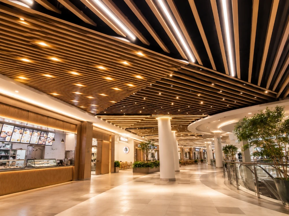
A reliable metal baffle ceiling takeoff starts with the number and length of visible rows, then adds carriers, hangers, connectors, trims, service interruptions, cutting allowance, and maintenance spares. Floor area alone cannot produce a dependable order because two rooms with the same square metres may use different baffle directions, profile lengths, edge setbacks, and joint patterns.
The baffle ceiling calculation should be tied to a marked reflected ceiling plan and an approved system layout. Every figure needs a clear basis: net design quantity, fabrication or installation allowance, and spare stock. This makes the takeoff easier to check before quotation and reduces last-minute additions during installation.
What Must Be Fixed Before the Takeoff Begins?
The metal baffle ceiling layout needs a stable datum and a confirmed profile before quantities are calculated. If spacing, direction, edge conditions, or service zones are still changing, the result should remain a preliminary estimate.
Which Room Dimensions Control the Row Layout?
Record the clear ceiling boundary, room length and width, baffle direction, centerline datum, perimeter setback, and every zone with a different elevation or orientation. Columns, bulkheads, skylights, curved edges, open voids, and ceiling steps need separate dimensions.
Direction matters because it determines each row length. In a long narrow room, rotating the baffles by 90 degrees may leave the total ceiling area unchanged while increasing the number of pieces, joints, and carrier intersections. The drawing should also confirm whether a baffle or a clear gap is centered on the room axis.
Which Profile and Spacing Values Must Be Confirmed?
Define baffle width, height, material, thickness, finish, perforation, supply length, and center-to-center spacing. The clear opening in a regular parallel layout equals the baffle ceiling spacing minus the profile width. A schedule that records only the visible gap is incomplete.
The TUODELI metal baffle ceiling systems include different linear forms, so the takeoff should identify the selected profile rather than use a generic description. Profile shape affects the compatible carrier, connector, end cap, joint treatment, packing method, and usable length.
Which Components Belong in the Quantity Schedule?
Separate visible components from concealed support parts. A ceiling material takeoff may include baffle lengths, carriers, suspension rods or wires, hangers, carrier splices, baffle connectors, end caps, perimeter trims, hold-down parts, access modules, and replacement stock. The final component list must match the selected system.
Lights, diffusers, speakers, sprinklers, signs, and access hatches should be marked before rows are measured. Some services sit within a gap, while others interrupt one or more baffles or require framed openings. Their effect belongs in the coordinated layout, not in an allowance added after ordering.

How Do You Calculate Rows and Linear Metres?
For a regular rectangular zone, keep all row calculations in millimetres and convert the final total into metres. The formula must follow the actual setting-out method rather than an assumed room-center arrangement.
How Is the Number of Rows Calculated?
Let W be the room dimension perpendicular to the baffles, e the centerline setback at both edges, and s the approved baffle ceiling spacing measured center to center:
Number of rows = floor((W − 2e) ÷ s) + 1
This formula applies when the first and last centerlines use the same setback. If the design centers a gap, uses unequal edges, or changes spacing near the perimeter, draw the centerlines individually and count them from the coordinated plan.
What Does a Rectangular-Room Example Show?
Consider an 18,000 × 12,000 mm room. The baffles run in the 18,000 mm direction, centerline spacing is 150 mm, and the first and last baffle centerlines are 75 mm from the side boundaries:
Rows = floor((12,000 − 150) ÷ 150) + 1 = 80
With no openings, the net design length is:
80 × 18 m = 1,440 linear metres
This is not yet the purchase quantity. It does not include joints, cutting optimization, damaged-piece contingency, service interruptions, or maintenance spares.
How Are Irregular Zones Measured?
Divide an irregular ceiling into numbered rectangles, trapezoids, curved bands, or stepped areas. Draw each baffle centerline, trim it to the boundary, and measure the resulting segment. This method captures tapered ends and staggered openings more accurately than multiplying area by a conversion factor.
Curved boundaries should be measured from coordinated CAD or BIM geometry rather than a scaled PDF. Very short end pieces may not provide enough engagement for the intended connector or closure. Flag those conditions for detail review before adding them to the order.
How Are Pieces, Joints, and Supports Optimized?
Net linear metres describe the design, while pieces and accessories describe what must be manufactured and installed. Optimization should consider supply length, transport, building access, joint locations, reusable offcuts, and the concealed support arrangement.
How Does Supply Length Affect Piece Count?
For each row, divide the net row length by the selected supply length, then check whether the remaining cut can begin another row. Avoid rounding every row independently before testing offcut reuse. A repeated 17.6 m row may create considerably more waste than an 18 m row when both are assembled from nominal 6 m pieces.
U-shaped baffles can be configured with widths and heights from 20 to 200 mm and lengths from 300 to 6,000 mm, subject to the selected material and system. Round profiles use their own diameter and length combinations. The round-tube aluminum baffle dimensions are therefore relevant only when the takeoff is built around that profile and its compatible suspension.
How Are Connectors, Carriers, and Hangers Counted?
Count baffle connectors from the optimized piece schedule. A row assembled from three pieces normally has two internal joints, subject to the approved connection detail. Add exposed end caps, transitions, special closures, and change-of-direction pieces separately.
Draw carrier lines perpendicular to the baffles using the verified system spacing. Measure the actual carrier length in each zone, convert it into supply pieces, and count splices from that cutting schedule. Hangers should then be plotted along every carrier using the approved maximum interval and required distance from carrier ends.
Carrier and hanger spacing cannot be derived from visible baffle spacing. Loads, substrate, services, access requirements, seismic criteria, and any wind conditions can change the support layout. Special anchors, trapeze supports, and secondary steel should remain separate scope items.
How Do Perimeters and Services Change the Count?
Measure perimeter trim along the actual boundary, including recesses, columns, returns, and ceiling steps. Do not rely on the nominal perimeter of a rectangular room when the finished ceiling line contains interruptions.
Large lights, diffusers, hatches, and signs may need extra carriers or framed openings. Small services may remove only a short baffle segment, while wider openings can interrupt several rows. Record these changes by zone so deleted baffle lengths and added framing do not cancel each other invisibly inside one allowance.
What Allowance Prevents Shortages Without Inflating Cost?
A single waste percentage is easy to apply but difficult to defend. Allowance should reflect cutting geometry, handling risk, batch matching, transport conditions, and the client’s spare-stock requirement.
Which Areas Need a Higher Cutting Allowance?
Straight repetitive zones using full or efficiently nested lengths may need only a limited contingency. Angled perimeters, curves, small infill areas, changes in direction, color transitions, service-heavy zones, and custom closures create more unusable offcut.
Keep separate columns in the ceiling material takeoff for net design quantity, cutting or installation allowance, and maintenance spares. This prevents future replacement stock from being mistaken for fabrication waste and makes every addition commercially visible.
Why Do Finish Batch and Transport Matter?
Ordering a small quantity of matching spares with the main production run may reduce the risk of a later color or gloss mismatch. The decision should consider the project’s replacement expectations and storage capacity rather than applying the same spare ratio to every zone.
Long baffles also need suitable crates, level supports, planned unloading, and a clear route to the installation area. Lift dimensions, turning space, and access doors may limit usable supply length. A theoretically efficient cutting plan can fail if the longest pieces cannot reach the workface without bending or surface damage.
How Should the Final Order Be Checked?
The last review should make every quantity traceable to a current drawing and a named ceiling zone. It should also identify which items belong to the ceiling supplier, installer, structure contractor, and service trades.
What Must the Final Schedule Contain?
List the zone reference, profile, width, height, material, thickness, finish, perforation, piece length, piece count, carrier type, suspension parts, trims, connectors, end treatments, allowances, and spares. Add the drawing revision and the date used for measurement.
The schedule should use the same profile codes and finish references as the approved sample and shop drawings. Unnamed “standard” parts make it difficult to detect incompatible carriers, missing accessories, or mixed finishes before delivery.
Which Documents Should Be Cross-Checked?
Compare the takeoff with the reflected ceiling plan, sections, room data sheets, lighting layout, mechanical drawings, fire-protection layout, and approved samples. The metal ceiling RFQ information checklist helps organize profile, finish, quantity, drawing, packing, and delivery information before quotations are compared.
Have a second person trace several representative rows from drawing to schedule and back again. Check the longest piece against transport and access limits, verify every special zone, and confirm that unit conversions have not changed millimetres into metres incorrectly.
What Is the Next Step After the Takeoff Is Ready?
Prepare the room dimensions, marked row layout, chosen profile, baffle ceiling spacing, finish, perforation requirement, supply lengths, and accessory schedule. These details allow the visible baffles and concealed suspension to be reviewed as one order.
Ready to turn the calculated quantities into a coordinated supply proposal? Submit the U-baffle specifications and length schedule for quotation before confirming production quantities, packing lengths, and delivery timing.
Conclusion
An accurate metal baffle ceiling quantity begins with the row layout rather than floor area alone. Establish the datum, direction, profile, spacing, perimeter conditions, and service zones first. Then calculate rows and net linear metres, optimize the piece schedule, and derive connectors from actual joints.
Carriers, hangers, trims, and special supports should follow the approved system arrangement. Separating net quantity, cutting allowance, logistics contingency, and maintenance spares makes the baffle ceiling calculation easier to audit and less likely to create shortages or unnecessary over-ordering.
FAQs
Q1: Can square metres be converted directly into metal baffle ceiling linear metres?
A1: Only for a preliminary estimate when the baffle spacing is fixed and the area is regular. Final quantities must account for direction, edge setbacks, openings, curves, joints, supply lengths, and different ceiling zones.
Q2: Is baffle ceiling spacing measured between faces or centerlines?
A2: It should be stated explicitly. Most row calculations use centerline spacing, while the visible gap equals centerline spacing minus the baffle width. Confusing these values changes the row count.
Q3: Should the same waste percentage be used for baffles and accessories?
A3: No. Baffle offcut depends on row and supply lengths, connectors follow actual joints, trims follow perimeter geometry, and maintenance spares are a separate requirement. Each group needs an allowance linked to its own risk.
Other News