Curved Metal Ceiling Design: Continuous Curves or Faceted Baffles?

A ceiling specified with a continuously curved line needs curved baffles. Straight sections are an alternative when the architect accepts the angular changes as part of the finished design. Our aluminum curved baffle ceiling provides a relevant option for the first requirement. The important distinction is geometric: joining several curved members can retain an arc, while replacing that arc with straight members changes its outline between the joints.
This choice belongs near the beginning of a curved metal ceiling design, before the team settles piece lengths. A distant rendering may make both arrangements look similar. Inspect the intended curve in section to decide whether they are interchangeable for the project. Decide which outline to preserve, then divide it into components that suit the selected profile and installation conditions.
Decide which line must remain curved
The phrase “curved appearance” leaves several possibilities open.
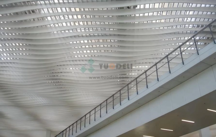
In plan, rows of baffles can sweep around a bend. In elevation, the members can rise and fall, or separate members at different heights can form a wave along their lower edges. Each arrangement needs a drawing that identifies the geometry. A supplier receiving only the description “wave ceiling” must still establish which parts are meant to bend.
Identify the particular line on which the design depends. In a corridor, it may be the plan path of a row. Across a reception area, it may be the bottom silhouette seen from the entrance. A sculpted field may depend on the relationship between neighboring rows. Mark that line in the relevant plan or section, with its direction and reference level. A perspective view can accompany it, but cannot establish the geometry by itself.
Our metal baffle ceiling range includes the curved aluminum form. For that product, widths of 50–300 mm and heights of 50–1,800 mm give the designer a range of section proportions to consider. Here, height and width describe the baffle section. They do not describe the rise across a ceiling field. A taller member exposes more side face, while the wave and the centerline path remain separate geometry decisions.
Orientation also belongs in the definition.
Dimension the plan radius for the path across the room and the elevation radius for the vertical outline. Curvature in both views may require a shape that cannot be described by a simple bend. Identify the required orientation with the selected profile before treating it as an accepted product configuration. The useful design instruction is the actual curve and cross-section together.
Retain continuous curvature if the approved appearance depends on a smooth lower edge, a sweeping row or a tangent transition. Angular changes can suit a deliberately faceted composition. Where an uninterrupted arc is required, straight sections remain a change to the design even when their ends occupy the correct positions.
An arc and its chords make different ceilings
Between any two points on a circle, there are two different paths to consider here: the straight chord and the circular arc.
A chord runs inside the arc, meeting it only at the ends. Check the midpoint of the straight length to find their greatest separation. End-joint checks alone cannot reveal what happens to the outline between those joints.
Use R for the circle radius and θ for the angle covered by a straight piece. With consistent angle units, R × [1 − cos(θ/2)] gives the midpoint gap. Even flawless manufacture and exact endpoint positioning leave this gap in place, because the design has substituted a straight length for a curve.
Take a hypothetical radius of 6 m with a ceiling arc covering 60 degrees. The distance along that arc is approximately 6.283 m, compared with 6 m directly between its ends. A single straight piece joining those ends would depart from the arc by approximately 804 mm at its midpoint. Accepting the same endpoints would therefore still leave a substantial change to the ceiling outline.
Splitting that total angle across additional straight pieces brings their outlines closer to the arc. The table shows ideal geometry for this example; its values are not recommended project tolerances or product performance claims.
Straight segments across the 60° curve | Angle per segment | Approximate maximum deviation from the arc |
One segment | 60° | 804 mm |
Two equal segments | 30° | 204 mm |
Six equal segments | 10° | 23 mm |
The reduction comes with additional direction changes.
With six segments, the approximation is closer, although each length is still straight. Whether the junctions remain evident depends on the view, adjoining rows and light along the edges. Even a modest geometric departure still needs visual assessment before the approximation is accepted as continuous in appearance.
Either outline can be a valid architectural choice once its consequences are accepted. A requirement for a smooth line, however, calls for curved members. Where angular changes are acceptable, depict each facet and review that version of the ceiling. Permission for “equivalent geometry” needs a narrower definition when the proposed shapes differ.
A curved metal baffle ceiling design with multiple rows also needs review across the field. Check how each row starts and which radius it follows before repeating a straight length across neighboring rows. That repetition can affect both spacing and end alignment. Specify the dimensioned reference as well: the centerline and exposed edge have different radii across a member's width.
The circular calculation does not define an ellipse, a free-form spline or another varying-radius curve. Such shapes require their corresponding control points and setting-out information. Keep that information in the schedule rather than substituting one radius. For each shape, judge the permissible departure from its design line alongside the effect that departure would have on the visible ceiling.
Divide the curved run without changing its shape
Once the team has chosen a genuine curve, component divisions can be considered without reopening the shape decision.
Several curved modules may follow one continuous design line. A joint introduces a material division without necessarily replacing a curve by a straight line. For the assembled outline to remain continuous, adjoining ends must meet with the intended position and curve direction.
At a shared endpoint, different curve directions produce a kink. The meeting point therefore needs an intended tangent direction as well as coordinates. Communicate both where the radius changes, and where a curved member transitions to a straight portion, to retain the smooth transition.
Our curved aluminum baffle product has a length range of 1,000–6,000 mm.
Start the component layout within that length range, allowing for several members along a room-length sweep. For the hypothetical 6 m radius, the arc measures 6.283 m while its chord measures 6 m. An order based solely on the 6 m endpoint distance would miss the additional length around the curve.
A drawing for that example could investigate three curved sections of approximately 2.094 m along the design line. This division is a geometry study, rather than a confirmed manufacturing arrangement. The project still needs the selected profile's length convention, curve orientation, radius and end details resolved together. A catalogue length may be described along a particular reference, so the drawing and order must use the same definition.
The product's aluminum thickness range of 1.50–5.00 mm also belongs to the profile selection. A thickness value alone cannot set the bending radius for every profile. The proposed curve has to be considered with its cross-section and thickness. Values chosen independently from the extremes of the ranges may not form a suitable combination. Review the section against the required shape, keeping that shape as the basis for the decision.
Locate joints against the principal contour first, then follow those divisions through the rest of the run. Shifting a joint clear of a prominent crest may benefit the main elevation but leave an awkward short length at the wall. Across neighboring rows, aligned joints and staggered joints also produce different visual rhythms. Let the intended ceiling composition determine which arrangement belongs there.
Connections and supports must follow the selected arrangement. A geometric model locates the meeting points. Hanger spacing, connection capacity and access clearances require their own support and installation decisions. Once the shape and preliminary divisions are established, resolve these supporting details against them. Any resulting change from a smooth outline to an angular one should remain visible for design review.
Freeze the silhouette before the product schedule
The decisive comparison should show the original curve and the proposed component outlines in the same view.
Hold the reference points, scale and camera position constant when comparing versions. Leave the straight edges visible in the faceted option so that the proposed geometry, rather than a graphically smoothed substitute, receives approval.
Review the principal viewing section together with an oblique view of the baffle sides. Curved modules can form a smooth lower edge even though their joints remain visible. Accepting a joint treatment therefore does not authorize replacing the member with a straight chord. Approve seam appearance and ceiling geometry as separate decisions.
Include the intended finish when reviewing reflective or directional surfaces. Under grazing light, an orientation change can be conspicuous even if the drawing suggests only a modest geometric departure. Where drawings leave the visual outcome uncertain, a representative assembled sample can help the project assess adjoining sections under relevant lighting. Define what that sample is meant to resolve before commissioning it.
Carry the accepted outline into the component schedule using curve and member identifiers.
A row containing several radii needs more than one repeated length description.
Give separate identifiers to members whose endpoints or orientations differ, even if they look alike. A later replacement request can then refer to that member's geometry instead of depending on a ceiling photograph.
Begin an enquiry to TUODELI with the curve that is to remain in the finished ceiling. Send the curve and viewing section, together with the proposed profile dimensions, finish, joint positions and quantities by geometry. The resulting discussion can focus on a curved-baffle proposal that preserves that outline, with any required shape changes made visible before a different ceiling is accepted.
Other News